
High-dimensional Interconnect Technology for the K Computer and the Supercomputer Fugaku
Release date: August 21, 2020
The K computer and its successor supercomputer “Fugaku” are world-class supercomputers that are massively parallel computers made up of 88,192 and 158,976 interconnected nodes respectively. This 100k-node scalability is made possible by an interconnect technology developed by Fujitsu that features high dimensionality. The partitioning and virtual torus functions of the technology prevent interference in the communications between multiple parallel programs and support optimization of communication patterns within each parallel program to ensure stable communication performance, and allow partitions to remain in use even when they contain failed nodes for high availability. This article describes the interconnect technology with high dimensionality used in the K computer and the supercomputer Fugaku.
- 1. Introduction
- 2. Past techniques and their problems
- 3. High-dimensional interconnect technology and its implementation
- 4. Interconnect performance
- 5. Conclusion
1. Introduction
World-class computer simulation is an essential tool for resolving complex social problems and for advancing state of the art science and technology. These large simulations are executed on machines called parallel computers. A parallel computer consists of a large number of nodes with processors and an internal network called an “interconnect” that connects these nodes together. Each processor executes its own small part of a calculation and the overall simulation is achieved by the nodes exchanging results and other data via the interconnect.
With 88,192 interconnecting nodes, the K computer [1,2] was one such massively parallel computer. It provided scientists and engineers from Japan and overseas with a world-class environment for computer simulation. Its successor, the supercomputer Fugaku [3], meanwhile, has 158,976 interconnecting nodes [4]. These are huge systems on the scale of a large data center and, along with an interconnect that delivers high-performance communications between nodes, their requirements include functions to support the optimization of communication patterns and prevent interference in the communications between parallel programs, and also high availability to maintain node utilization and prevent system shutdowns.
This article describes the high-dimensional interconnect technology used to achieve the interconnect in the K computer and Fugaku. The following section describes techniques used in the past and their associated problems, section 3 describes the high-dimensional interconnect and its implementation, section 4 presents results of its use, and the final section summarizes this article and describes the future vision.
The author of this article was awarded a Medal of Honor with Purple Ribbon in the 2020 Spring Conferment for his development of high-dimensional interconnect technology for massively parallel computers [5].
2. Past techniques and their problems
Interconnects that connect hundreds or thousands of nodes have, to date, mainly used networks with the “fat-tree” or “folded Clos” topologies that consist of multiple levels of network switches. In fact, the development of interconnects capable of surpassing the fat-tree configuration has been one of the major technical challenges facing the field of world-class supercomputers. When the development of the technology described in this article began in 2005, three-dimensional interconnects capable of connecting more than 10,000 nodes were successfully implemented. IBM’s Blue Gene/L announced in 2004 [6], for example, achieved performance exceeding that of the first-generation Earth Simulator (a Japanese supercomputer) by connecting 32,768 nodes with embedded processors. Similarly, Red Storm announced by the US company Cray Inc. in 2005 [7] connected 10,880 nodes with off-the-shelf processors.
In a three-dimensional interconnect, each node has its own network router and the nodes connect to each other in a three-dimensional lattice. The network is called a three-dimensional torus if each dimension is connected in a loop and a three-dimensional mesh if open ended. Figure 1 shows a diagram of a 4 × 4 × 4 three-dimensional torus. Different design concepts apply depending on whether a torus or mesh configuration is used, with each having its own particular issues.
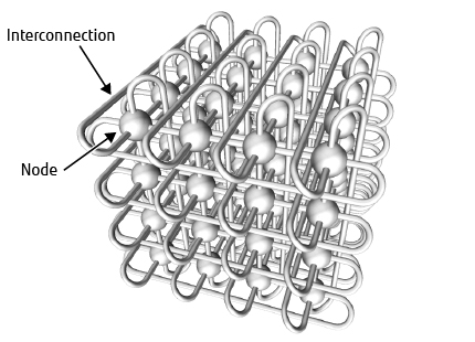
Figure 1 Diagram of three-dimensional torus.
Systems like the Blue Gene/L that use a three-dimensional torus include a function for dividing the system into partitions in such a way that each partition still forms a three-dimensional torus. Each parallel program executes in its own partition where it is not subject to communications interference from other parallel programs. The three-dimensional torus topology is well-suited to applications that simulate three-dimensional spaces. Furthermore, efficient data transfer is easy to program because each dimension of the network is symmetrical in the sense that there is no difference in location such as edge or middle. To facilitate partitioning, three-dimensional torus systems are built from fixed-size (8 × 8 × 8, for example) three-dimensional mesh blocks, with the edges of each dimension of each block connecting to a partition switch. The problem with this is that a failure in one node takes its entire block out of service, including all the block’s other non-failed nodes, thereby significantly reducing the number of nodes available to the system.
The Cray XT series, the production version of Red Storm, uses a three-dimensional mesh without partitions, with parallel-executing programs using available nodes scattered across the system. While this avoids the problem of failed nodes degrading availability, it makes it difficult to optimize communications performance by assuming a three-dimensional network. Worse, because multiple parallel programs execute on the three-dimensional network, it introduces a new problem of performance degradation due to communication interference. Moreover, this problem of communication interference is further exacerbated on a three-dimensional mesh system by the need to detour data communications in the vicinity of any failed nodes, which is necessary because the adjacent nodes remain in use.
3. High-dimensional interconnect technology and its implementation
High-dimensional interconnect technology uses a six-dimensional mesh/torus network to provide scalability that is an order of magnitude greater than the previous three-dimensional interconnect. The network consists of groups of 12 nodes that connect to each other in three dimensions. Figure 2 shows a diagram of the six-dimensional mesh/torus network. X, Y, and Z represent the coordinate axes of the three-dimensional connections between groups, and A, B, and C represent the coordinate axes of the three-dimensional connections within groups. The 12 nodes in a group are interconnected in a three-dimensional lattice, with two nodes in the A axis, three in the B axis, and two in the C axis. Systems that use this six-dimensional mesh/torus have a partitioning function to resolve the problem of communications performance degradation as in systems with a three-dimensional torus, while regions that contain a failed node are able to remain in use as in three-dimensional mesh systems thereby also overcoming the problem of degraded availability.
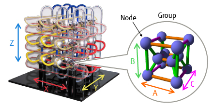
Figure 2 Diagram of six-dimensional mesh/torus.
The six-dimensional mesh/torus can be partitioned at any location along group boundaries. Because this partitioning can be more fine-grained than is possible with a three-dimensional torus and eliminates the need for partition switches, parallel programs with various levels of parallelism can execute concurrently without their internal communications interfering with each other. Moreover, the high dimensionality increases the number of links, all of which are available for communication. This improves communication performance because the paths between nodes are shorter and there is less communication congestion.
While each parallel program runs a single six-dimensional partition, the virtual three-dimensional torus function allows three-dimensional coordinates to be used for nodes. This is done in a way that guarantees that nodes that are adjacent in terms of their three-dimensional torus coordinates are also adjacent in the actual six-dimensional network. This function allows the communication performance of parallel programs to be optimized as if the programs were executing in a three-dimensional torus. The virtual three-dimensional torus function divides the actual six-dimensional network into three sets of two-dimensional spaces and assigns coordinates on the basis of treating a single cyclic path that visits all of the nodes in one of these two-dimensional spaces exactly once (a Hamiltonian cycle) as one virtual dimension. If a partition contains a failed node, it is still able to be used as long as a Hamiltonian cycle that avoids the failed node can be formed through one set of two-dimensional spaces. Moreover, the presence of the B-axis, which is a physical dimension of size three, means that partitions that contain a single failed node are guaranteed to remain usable. Whether or not partitions that contain more than one failed node are still usable, however, depends on the locations of the failed nodes.
This configuration was first used on the Tofu interconnect for the K computer [8], [9], [10]. The name “Tofu” is an abbreviation of “torus fusion.”. The Tofu interconnect was implemented on a dedicated interconnect controller (ICC) and featured wide throughput, with a maximum injection bandwidth of 20 GB/s and a maximum switching capacity of 140 GB/s. The supercomputer Fugaku has been enhanced to use the latest Tofu interconnect D [11] (the “D” stands for “high density”). Tofu interconnect D is implemented on the A64FXTM CPU and its performance has been enhanced to a maximum injection bandwidth of 40.8 GB/s and a maximum switching capacity of 217.6 GB/s. Figure 3 and Figure 4 show die photographs of the ICC and A64FX CPU respectively.
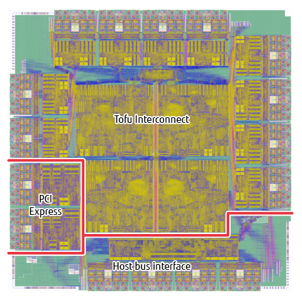
Figure 3 ICC die.
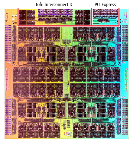
Figure 4 A64FX CPU die.
Whether or not the X, Y, and Z axes of the Tofu interconnect are connected in a loop is configurable on a system-by-system basis to allow for different implementation and operational considerations. In the configuration used by the K system, for example, the X axis was connected in a loop to prevent it from being split up when parts of the system were shut down for maintenance, the Y axis was left open ended to allow for system expansion, and the Z-axis was connected in a loop to ensure a short communication path for input and output nodes located at the zero position on the axis.
4. Interconnect performance
Shipment and configuration of the K computer got underway in 2010, with operation officially commencing in 2012. The K computer made of 88,192 interconnected nodes was made possible by the high degree of scalability, flexible partitioning function, and high availability of the Tofu interconnect built using the techniques described in this article. The supercomputer has been used by scientists and engineers working in a wide range of fields at research institutions, universities, and companies, including drug development, the study of earthquakes and tsunamis, weather, space, manufacturing, and materials development. It has achieved a high level of system utilization exceeding 97% excluding scheduled maintenance. The performance of the Tofu interconnect has also contributed to the K computer recording world-leading performance at benchmarks such as Graph500 [12] and HPC Challenge Global FFT [13] that emphasize interconnect performance. The K computer ceased operation in 2019. The technology was also awarded the 2014 Imperial Invention Award [14].
Shipment of the K computer’s successor, Fugaku, commenced in 2019. The new supercomputer used the Tofu interconnect D to connect a total of 158,976 nodes. The technology was announced in 2009 as being intended to support world-class supercomputers as they reach the exascale class [8]. The goal of this technology will be achieved by the successful commissioning of the Fugaku, the successor to the K computer that is based on the same technology.
New technological trends that have arisen in the field of microelectronics over recent years include a slowing of semiconductor miniaturization and the emergence of high-density packaging techniques. Meanwhile, the computer science and engineering field has seen growing interest in domain-specific architectures for technologies such as AI. This means that the supercomputers to come after the Fugaku will require new system architectures and interconnects that are suited to these changing trends.
5. Conclusion
This article described the high-dimensional interconnect technology that features scalability, a flexible partitioning function, and high availability. The interconnect provides the K and Fugaku systems with excellent reliability, featuring stable communication performance and easy communication optimization as well as scalability. The author would like to take this opportunity to sincerely thank everyone involved for their extensive efforts over many years.
Having played an important role in the field of supercomputing for many years, Fujitsu has contributed to resolving challenges facing society and to advancing science and technology. Through the success of the K computer and the successful completion of the supercomputer Fugaku, Fujitsu looks forward to continuing to play this important role into the future.
All company and product names mentioned herein are trademarks or registered trademarks of their respective owners.
References and Notes
- N. R. Adiga et al.: An Overview of the BlueGene/L Supercomputer. Proceedings of the SC 2002 Conference on High Performance Networking and Computing (2002).Back to Body
- R. Alverson: Red storm. Hot Chips 15 (2003).Back to Body
- Y. Ajima et al.: Tofu: A 6D Mesh/Torus Interconnect for Exascale Computers. IEEE Computer, Vol. 42, No. 11, pp. 36–40 (2009).Back to Body
- Y. Ajima et al.: The Tofu Interconnect. IEEE 19th Annual Symposium on High Performance Interconnects, pp. 87–94 (2011).Back to Body
- Y. Ajima et al.: “Tofu: Interconnect for the K computer.” FUJITSU Sci. Tech. J., Vol. 48, No. 3, pp. 280–285 (2012).Back to Body
- Y. Ajima et al.: The Tofu Interconnect D. IEEE International Conference on Cluster Computing, pp. 646–654 (2018).Back to Body
About the Authors

Dr. Ajima is currently engaged in the development of supercomputer architectures.