
System Implementation Technologies of Supercomputer Fugaku
Release date: November 11, 2020
The supercomputer Fugaku (hereafter, Fugaku) achieved the world’s top position in four categories of computing performance according to supercomputer rankings announced in June 2020.The prototype of Fugaku also won the world’s first place in the performance per power consumption ranking announced in November 2019. Realization of such high performance and power saving owes not only to the performance of the newly developed CPU but also the system implementation technologies such as the four times larger number of CPUs per rack mounted as compared with predecessor K computer.
This article describes the system implementation technologies that have allowed for the high performance and power saving seen in Fugaku.
- 1. Introduction
- 2. System implementation technologies to support performance enhancement
- 3. System implementation technologies to support power saving
- 4. Conclusion
1. Introduction
The supercomputer Fugaku (hereafter, Fugaku) has realized the world’s highest computing performance and the world’s top class power consumption performance.
Personal computers, which are a familiar type of computers, often have only one CPU, so their computing performance depends on the performance of that CPU. Supercomputers, on the other hand, have a massive number of CPUs because supercomputers are required to offer ultra-high-speed computing capability. Therefore, the computing performance greatly depends on the interconnect performance between CPUs as well as the CPU performance. Therefore, high-density mounting is needed to mount CPUs closer to each other.
In addition, realization of the world’s top level power consumption performance requires thoroughgoing reduction of power losses over the entire system as well as power saving by the CPUs.
This article explains the features of the housing used in the Fugaku and describes the system implementation technologies that support performance enhancement and power saving.
2. System implementation technologies to support performance enhancement
Supercomputers that enhance performance by connecting together a large number of CPUs such as Fugaku require high-density mounting to enable high-speed data communication between CPUs. This section first presents the structure used by Fugaku. Then, it describes the issues to be resolved to realize high-density mounting and the technologies for resolving those issues.
2.1 Structure used by Fugaku
Figure 1 shows the structure of the housing used by Fugaku. A CPU memory unit (CMU) containing two CPUs (each CPU integrating four stacked memory devices) form the basic unit. A total of 192 CMUs are mounted in a rack with 96 on the front and the rear sides respectively. A CMU is equipped with high-speed communication connectors for connection at the center of the rack on the back side, and liquid cooling piping and high-speed communication cabling for connection on the front side.
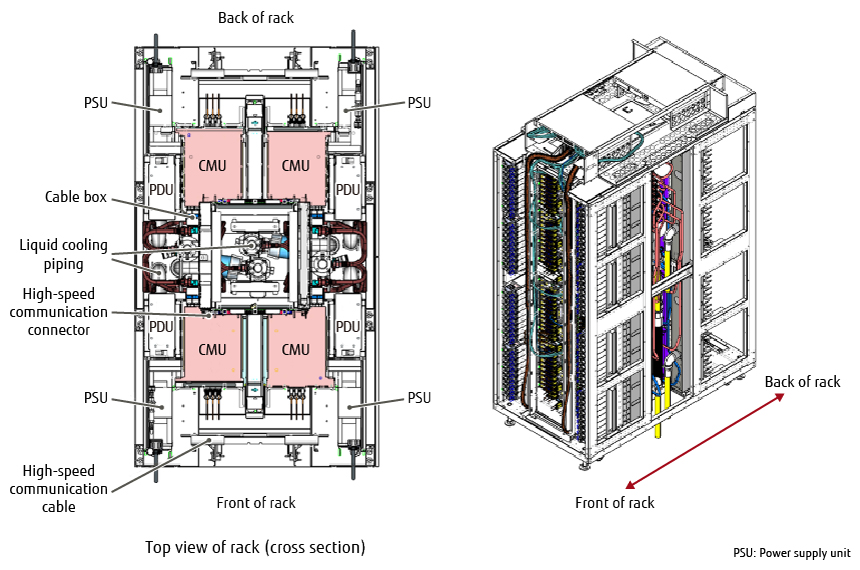
Figure 1 Housing configuration.
2.2 Issues in achieving higher density
This subsection describes two system implementation issues in achieving high computing performance in Fugaku.
1) Realization of efficient liquid cooling with low flow rates
In order to enhance performance, Fugaku has four times the number of CPUs than that of the K computer. In addition, the performance of the CPU itself has been improved and the amount of heat generated per CPU is larger. As a result, heat generation per rack is about six times as large as that of the K computer and improvement in the cooling performance is required. Generally, cooling is improved by increasing the flow rate of cooling water. However, this necessitates larger-diameter piping and hinders high-density mounting, which is the original objective. Therefore, realization of efficient liquid cooling with low flow rates is an issue.
2) Live maintenance in limited work space
With Fugaku, maintenance of CMUs requires live maintenance, which is maintenance work conducted while the system itself continues operating. However, a CMU has many connections such as those for high‐speed signals, liquid cooling piping, and power, and these must be inserted and removed during maintenance. Sufficient work space must be secured to allow for live maintenance, and this space hinders high-density mounting. Accordingly, live maintenance in limited work space poses an issue.
2.3 Technologies for achieving higher density
This subsection presents the technologies that resolve the two issues mentioned in the previous section and allow for increased speeds.
1) Realization of efficient liquid cooling with low flow rates
In order to realize high CPU cooling performance with low flow rates, we developed a new high-efficiency cooling unit and designed piping to reduce the difference between flow rates of multiple CMUs.
- High-efficiency cooling unit
Cooling units for cooling CPUs generally use a system that distributes the cooling water entering from inlets on one side to the whole unit and discharges it from outlets on the other side. This system was adopted by the K computer.
Meanwhile, the liquid cooling unit (LCU), which is the cooling unit used in Fugaku, employs a flow path structure in which the cooling water from the inlet is concentrated to the center of the unit and turned back on either side to cool the outside before being discharging, as shown in Figure 2. This increases the flow velocity of the cooling water, which improves cooling. In addition, the water flows in through the central part, which has a higher heat generation density, allowing for more efficient cooling.
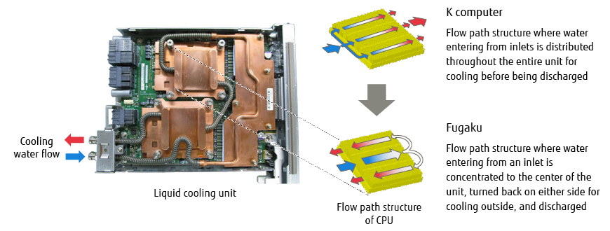
Figure 2 Flow path structure of liquid cooling unit.
- Piping design to reduce flow rate difference
On a Fugaku rack, 192 CMUs are mounted with 96 on each of the front and the rear sides. The height difference between the CMUs mounted at the top and the bottom can be as large as about 2 m. This causes a difference in the rates of flow into CMUs because of the water pressure difference due to gravity. In order to solve this problem, we divided the points of water flow diversion to individual CMUs into primary and secondary branch pipes and adjusted the length of the piping connecting the primary and the secondary pipes, thereby keeping the flow rate difference within ± 5%(Figure 3).
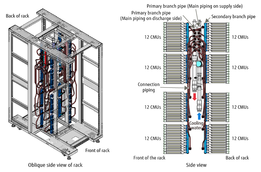
Figure 3 Liquid cooling system with uniform flow of cooling water.
2) Realization of live maintenance in limited space
In order to realize live maintenance of CMUs—which have many connections such as those for high-speed signals, liquid cooling piping, and power—in limited work space, we developed an electrical-water collective fitting system to allow multiple connections to be made simultaneously and a movable cable guide.
- CMU electrical-water collective fitting system
Fugaku has 96 CMUs mounted on the front and the rear sides of each rack respectively. For make replacing CMUs easier, the piping and high-speed communication and power supply cables are integrated inside the equipment. This both reduces size and improves availability at the same time. Adoption of the same water supply system as that of the K computer would require mounting and maintenance work areas for piping, which makes high-density mounting difficult. To solve this problem, electrical connectors and liquid cooling connectors must be fit together collectively.
For collective fitting, the liquid cooling connectors, which have no alignment function, must be newly provided with such function. While the connector angle was conventionally adjusted manually when inserted, Fugaku employs an original floating structure for the liquid cooling connectors. That is, by allowing the liquid cooling connectors three degrees of freedom (rotation and translation), multiple connectors, including liquid cooling connectors, are fitted into the normal positions by their respective guide functions when the unit is inserted (Figure 4).
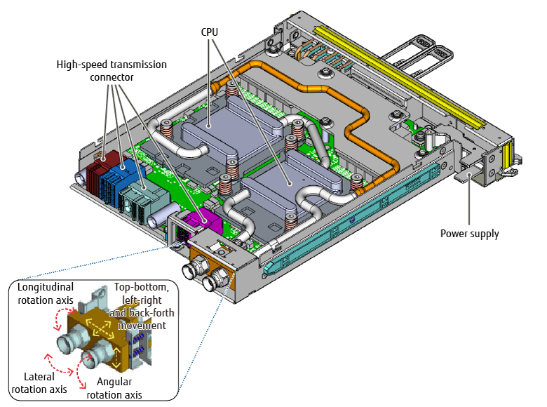
Figure 4 Liquid cooling connector floating mechanism.
- Movable cable guides
The K computer and existing models required a CMU replacement work area separate from the cable forming area for bunding and fixing the cables. With Fugaku, we developed a movable cable guide to provide a shared area. This allows the cable forming area to be used as the replacement work area as well. Reducing space in this way has led to the achievement of higher-density mounting (Figure 5). Cable guides are normally placed in front of the CMUs so as not to affect the air discharge from air-cooled boot I/O units (BIOUs). For replacement of any CMU, the cable guide can be moved toward the center, which allows for sufficient work area, making smooth and quick replacement possible.
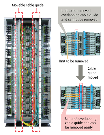
Figure 5 Movable cable holder.
By using the system implementation technologies mentioned above, liquid cooling has been improved, and the space not involved with computation has been reduced as much as possible, which allows for CPUs to be mounted at a greater density. This has made it possible to shorten the connection distances between CPUs and successfully achieve the world’s fastest CPU computing capability.
3. System implementation technologies to support power saving
In order to realize the highest power consumption performance in the world, thorough power saving over the whole system, as well as the CPUs, is required. It has been proven that the power losses generated in the system other than those generated by CPUs are mainly caused by power supply units (PSUs) and power supply circuits (DC-DC converters). Power saving therefore requires the reduction of power losses due to PSUs and between PSUs and CMUs.
This section describes the technological developments carried out to reduce power losses.
3.1 Reduction of power losses due to PSU
A PSU has two output circuits; they are the main and standby systems. Conventional power saving measures involved power loss reductions with a focus on the main output circuit. With Fugaku, we worked on power loss reductions related to the standby output circuit, which was rarely handled in the past, in addition to the main output circuit.
In order to reduce the power losses of the standby output circuit, an original Fujitsu standby circuit switching system was devised. In this system, the operation of the standby output circuit is stopped when the main output circuit is enabled, and the output is bypassed from the main output circuit to the standby circuit. In this way, all of the power losses due to the standby output circuit have been eliminated, achieving a significant reduction in power losses.
For the main output circuit, the latest high-efficiency circuits such as semi-bridgeless power factor correction (PFC) and phase-shift full-bridge circuits have been adopted to reduce power losses. In addition, measures have been taken including the reduction of the recovery current and other major switching losses by adopting a low-loss semiconductor (super junction FET), a new power device, and pattern loss reduction through optimization of the parts layout.
By employing Fujitsu’s original circuit system and the latest high-efficiency circuits described up to now, power losses due to PSUs have been halved from 9% to 4%, and the power conversion efficiency has been improved to a world-class level.
3.2 Reduction of power losses between PSUs and CMUs
With the K computer, the paths between the PSUs and CMUs were long because PSUs were arranged in a centralized manner (Figure 6). The power to the CMUs was supplied at a high voltage of 48 V because the current flowing through these paths caused large power losses and voltage drops. Therefore, supplying power to a DC-DC converter with a 12-V input required the provision of a bus converter, a voltage conversion circuit, resulting in a two-stage configuration (Figure 7). However, because bus converters have large power losses, we worked to reduce bus converters as well as reduce the power losses between PSUs and CMUs.
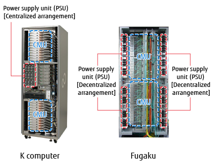
Figure 6 PSU arrangement.
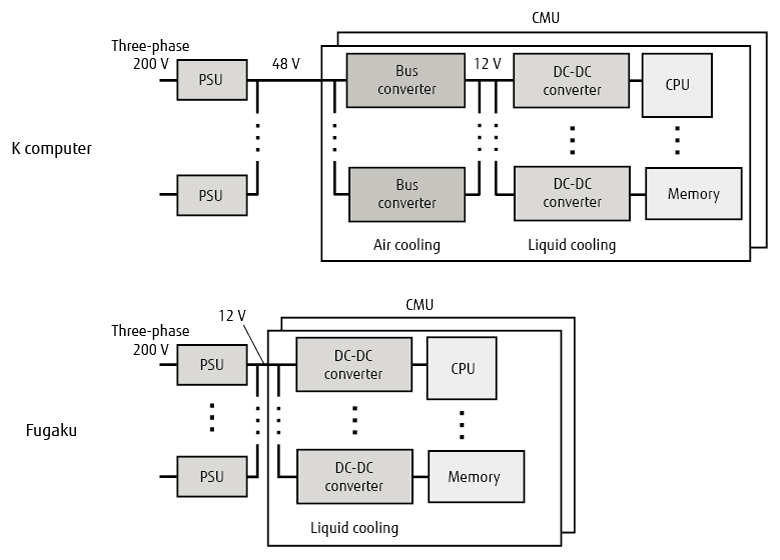
Figure 7 Power system configuration.
As shown in Figure 6, Fugaku has the PSUs arranged in a decentralized manner on the two sides of the rack, which successfully shortened the distances between all PSUs and CMUs to one fifth of the conventional distance on average. In this way, power losses between the PSUs and the CMUs have been reduced to allow 12-V power to be supplied to the CMUs. Bus converters, which were required for the K computer, have also been reduced to improve power losses. Furthermore, we also reduce the power losses related to DC-DC converters by adopting the latest devices. In total, these measures have resulted in a power loss reduction from 16% to 10%.
As a result of the technological development described above, the total power losses of the entire system have significantly improved from the conventional 24% to 14%.
4. Conclusion
This article has described the system implementation technologies that allowed for both the high performance and power saving of the Fugaku supercomputer and its ease of replacement simultaneously at a high level by presenting specific examples.
Recently, system requirements for high performance and power saving are increasing, not just for supercomputers but server devices in general. We intend to continue developing technologies to meet the requirements of the future.
All company and product names mentioned herein are trademarks or registered trademarks of their respective owners.
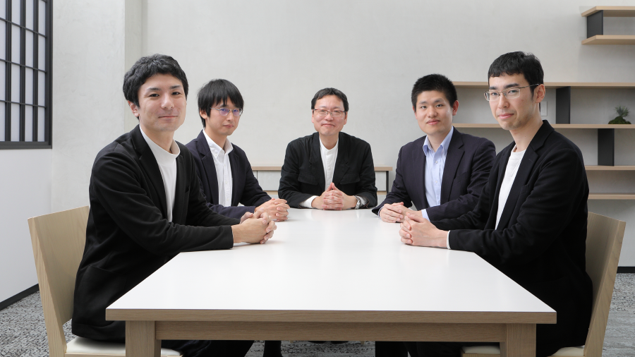
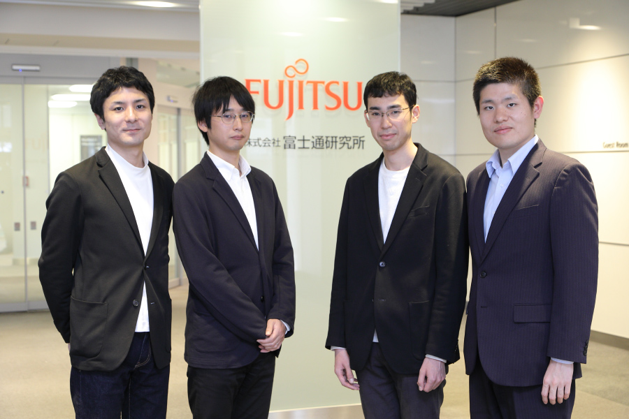
About the Authors
Mr. Eguchi is currently engaged in the development of power supply technology for server devices.
Mr. Umematsu is currently engaged in the development of structural technologies for implementing server devices.
Mr. Ohshima is currently engaged in the development of cooling technologies for server devices.